

Master crystal component terminology with this technical guide. Ensure accurate designs and avoid costly oscillator failures with essential definitions.
Crystal component terminology refers to the standardized set of definitions engineers and technicians use to specify, evaluate, and design electronic quartz crystal resonators and oscillators. Getting these terms right matters more than most datasheets suggest. A misunderstood load capacitance value or a misapplied ESR margin can cause an oscillator to fail at startup, and that failure often shows up only after a board is assembled. This guide covers every core term you need, from aging to Q factor, aligned with IEC TS 61994-4-1:2018 and industry-standard electrical models.
Crystal component terminology: the complete glossary
The definitions below follow the equivalent circuit model of a quartz crystal, which consists of a motional arm (L1, C1, R1) in parallel with a shunt capacitance (C0). Each term maps directly to a measurable parameter or a design decision.
-
Aging. The relative change in operating frequency over a specified time period, expressed in parts per million (ppm). Aging rate is highest in the first week after manufacture, then decreases gradually. Manufacturers typically calculate aging over the first 30 days and project it over one year or ten years. Seal integrity, operating temperature, and material type all affect the rate.
-
Baud rate. The number of signal changes per second in a data transmission system. In oscillator-driven circuits, the crystal’s frequency stability directly limits the maximum reliable baud rate. A crystal with poor short-term stability introduces timing jitter that corrupts high-speed serial data.
-
Crystal oscillator. An electronic circuit that uses the mechanical resonance of a quartz crystal to generate a stable frequency signal. The quartz crystal blank has electrodes deposited on both sides; when an alternating voltage is applied, the piezoelectric effect drives the blank into mechanical vibration at its resonant frequency.
-
Drive level. The power dissipated within the crystal, measured in microwatts (µW) or milliwatts (mW). Excessive drive level causes nonlinear behavior and can physically fracture the quartz blank through mechanical overstress. The crystal manufacturer specifies a maximum drive level for each product line, and the oscillator designer must verify that the actual power delivered to the crystal stays below that limit.
-
Equivalent series resistance (ESR). The resistive element R1 in the motional arm of the crystal’s equivalent circuit, measured in ohms. ESR typically ranges from 25Ω to 100Ω for most crystals. At series resonance, L1 and C1 cancel each other, leaving only R1 as the effective impedance. High ESR reduces the oscillator’s gain margin and is the most common cause of startup failure.
-
Equivalent series capacitance (C1). Also called motional capacitance, C1 represents the elasticity of the vibrating quartz. It is the capacitive element in the motional arm of the equivalent circuit. C1 for fundamental mode crystals typically ranges from approximately 0.005 pF to 0.030 pF. Electrode area, wafer thickness, and crystal cut all influence C1.
-
Frequency (f0). The nominal resonant frequency of the crystal, specified in hertz (Hz), kilohertz (kHz), or megahertz (MHz). This is the frequency at which the crystal is calibrated during manufacturing, referenced to a standard temperature of 25°C.
-
Frequency tolerance. The maximum allowable deviation of a crystal’s actual frequency from its nominal value at room temperature, expressed in ppm. Tolerance and stability are related but distinct: tolerance describes the manufacturing spread at 25°C, while stability describes behavior across the operating temperature range.
-
Frequency stability. The amount of frequency variation caused by changes in operating temperature, expressed in ppm relative to the frequency at 25°C. Stability depends on crystal cut, vibration mode, wafer dimensions, load capacitance, and drive level.
-
Frequency voltage characteristics. The relationship between supply voltage variation and the resulting frequency shift in an oscillator. Voltage-controlled crystal oscillators (VCXOs) exploit this relationship intentionally; standard oscillators treat it as an error source to minimize.
-
Fundamental mode. The lowest-frequency resonance of a crystal blank, where the thickness of the wafer equals one half-wavelength of the acoustic wave. Fundamental mode operation produces the lowest ESR and the highest Q of any resonance mode for a given blank geometry.
-
Hertz (Hz). The SI unit of frequency, equal to one cycle per second. Crystal frequencies span from a few kilohertz for low-frequency tuning fork designs to hundreds of megahertz for overtone resonators.
-
Insulation resistance. The DC resistance measured between the crystal’s terminals and its case or between terminals, typically specified in megaohms (MΩ) or gigaohms (GΩ). Low insulation resistance introduces leakage paths that can shift the operating frequency or prevent oscillation entirely.
-
Load capacitance. The external capacitance presented to the crystal by the oscillator circuit, measured in picofarads (pF). Load capacitance is not an intrinsic crystal property; it depends on PCB layout, discrete capacitors, and semiconductor pin capacitance. The crystal vendor calibrates the device at the specified load capacitance during manufacturing.
-
Motional inductance (L1). The inductive element in the crystal’s motional arm, representing the vibrating mass of the quartz blank. L1 values range from a few millihenries at high frequencies to several henries at low frequencies. L1 and C1 together determine the series resonant frequency.
-
Shunt capacitance (C0). The static capacitance between the crystal’s electrodes, present whether the crystal is oscillating or not. C0 arises from the electrode geometry and the crystal holder. Typical values range from 1 pF to 7 pF. C0 forms a parallel resonance with L1 at the anti-resonant frequency, above the series resonant frequency.
-
Overtone mode. A higher-order resonance of the crystal blank, occurring at approximately odd multiples of the fundamental frequency (3rd, 5th, 7th, 9th overtone). Overtone modes are not exact harmonics because the acoustic velocity in quartz is slightly dispersive. ESR increases with each overtone, and C1 decreases significantly compared to fundamental operation.
-
Temperature coefficient. The rate of change of resonant frequency with temperature, expressed in ppm/°C. The AT-cut is the most widely used crystal cut because its temperature coefficient passes through zero near 25°C, producing a cubic frequency-temperature curve with a relatively flat region across the commercial temperature range.
-
Temperature compensation. A circuit technique that applies a corrective voltage or reactive element to counteract the crystal’s frequency-temperature drift. Temperature-compensated crystal oscillators (TCXOs) use a thermistor network or digital lookup table to generate a compensation signal, achieving stabilities in the low-ppm range across wide temperature ranges.
-
Quality factor (Q). The ratio of energy stored to energy dissipated per cycle in the resonator. A higher Q means less frequency shift for a given change in load capacitance or external circuit conditions. Quartz crystals achieve Q values from 10,000 to 100,000, far exceeding LC tank circuits.
How crystal resonators actually work
A quartz crystal resonator is a precisely cut piece of piezoelectric quartz enclosed in a sealed package. When an alternating electric field is applied across the electrodes, the quartz blank deforms mechanically. At the resonant frequency, this mechanical vibration becomes self-sustaining and extremely stable, because the elastic properties of quartz are among the most consistent of any material used in electronics.
The cut angle of the blank determines almost everything about its frequency-temperature behavior. The AT-cut, sliced at approximately 35°15’ from the Z-axis of the quartz crystal, is the dominant choice for room-temperature and industrial applications. Its frequency-temperature curve is a third-order polynomial that can be flattened to within a few ppm across the 0°C to 70°C commercial range. The BT-cut offers a simpler quadratic curve but is less stable over wide temperature swings. For a deeper look at how crystal geometry connects to decorative and optical crystal terminology, Crystalplace’s crystal terminology guide draws useful parallels between optical and structural crystal concepts.
Pro Tip: When reviewing a crystal datasheet, check whether the frequency-temperature stability specification applies to the fundamental mode or the overtone mode. Overtone crystals have a different temperature curve than fundamental designs at the same nominal frequency, and mixing them up in a TCXO design produces compensation errors that are difficult to diagnose.
Series and parallel resonance are the two operating modes an oscillator circuit can use, and they are not interchangeable without recalibration. Series-resonant crystals present minimum impedance at the series resonant frequency and require no external reactive components in the feedback loop. Parallel-resonant crystals rely on external load capacitance to form an LC tank with the crystal’s motional inductance, pulling the operating frequency slightly above series resonance.
The equivalent circuit of a quartz crystal consists of a motional arm (L1, C1, R1 in series) placed in parallel with the shunt capacitance C0. Between the series resonant frequency and the anti-resonant frequency, the crystal appears inductive. This narrow inductive region is where parallel-resonant oscillators operate, and its width is controlled by the ratio of C0 to C1.
The practical consequence of this model is that any change in the external circuit’s reactive components shifts the operating point within the inductive region, changing the output frequency. That sensitivity is both the mechanism behind voltage-controlled oscillators and the source of frequency errors when PCB layout deviates from the design intent.
Electrical and mechanical parameters that define oscillator performance
Motional parameters: L1, C1, and R1
The motional arm of the crystal’s equivalent circuit encodes the crystal’s physical properties as electrical quantities. L1 represents vibrating mass, C1 represents quartz elasticity, and R1 represents mechanical losses within the blank and holder. These three parameters together set the series resonant frequency and the ESR.
C1 is the most design-sensitive of the three. Its value determines how much the crystal’s frequency can be pulled by an external load capacitance, a property called trim sensitivity. Smaller C1 means lower trim sensitivity and better immunity to circuit variations, but it also means less pullability for VCXO applications.
Load capacitance and frequency accuracy
Load capacitance is the single most common source of frequency error in production designs. The crystal vendor calibrates the device at a specified load capacitance, typically 8 pF, 12 pF, 18 pF, or 20 pF. If the actual PCB presents a different capacitance, the oscillator runs at the wrong frequency. Deviations in load capacitance require manual trimming to correct, which adds cost and time to production.
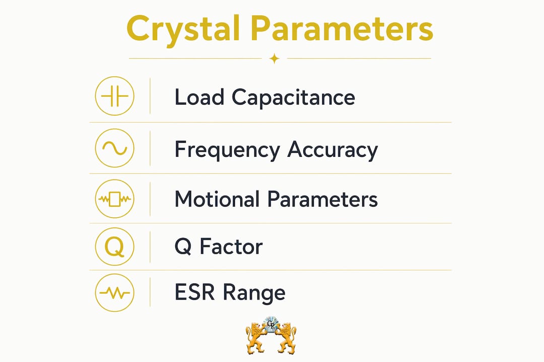
The total load capacitance includes discrete capacitors, stray board capacitance, and the Miller capacitance of the amplifier’s input and output pins. As a practical starting point, stray capacitance is often assumed to be approximately 5 pF, but that figure varies with package type, board material, and trace routing.
| Parameter | Typical Range | Design Implication |
|---|---|---|
| ESR (R1) | 25Ω–100Ω | Must be well below oscillator’s negative resistance |
| Motional capacitance (C1) | 0.005 pF–0.030 pF | Controls trim sensitivity and pullability |
| Shunt capacitance (C0) | 1 pF–7 pF | Affects anti-resonant frequency and oscillator tolerance |
| Load capacitance is specified by the crystal vendor and must be matched precisely by the oscillator circuit to ensure frequency accuracy. | ||
| Q values for quartz crystals are generally high, providing better frequency stability compared to standard LC tank circuits. |
Q factor and oscillator stability
Q is the ratio of energy stored to energy dissipated per cycle. In the equivalent circuit, Q equals the reactance of L1 divided by R1 at the series resonant frequency. A crystal with Q of 100,000 has a reactance-to-resistance ratio that no LC tank circuit can approach, which is why quartz oscillators achieve frequency stabilities that discrete component circuits cannot replicate in volume production.
The practical effect of high Q shows up in the steepness of the crystal’s reactance-versus-frequency curve. A steep slope means that a small frequency deviation produces a large change in reactance, which the oscillator circuit corrects quickly. Low-Q resonators have a shallow slope, so the circuit tolerates larger frequency errors before correcting them.
Drive level and crystal reliability
- Calculate the power delivered to the crystal from the oscillator circuit. For a parallel-resonant design, crystal current equals the RMS voltage across the load capacitor divided by the load capacitor’s reactance at the operating frequency.
- Compare the calculated power to the manufacturer’s maximum drive level specification. The limit is typically stated in microwatts for low-frequency crystals and milliwatts for higher-frequency devices.
- Add a margin of at least 3 dB below the maximum. Crystals operated near their drive level limit age faster and exhibit nonlinear frequency behavior.
- For overtone crystals, recalculate drive level at the overtone frequency, not the fundamental. ESR is higher at overtone modes, so the same current produces more power dissipation.
Frequency tolerance vs. frequency stability
These two specifications are often confused on datasheets. Frequency tolerance is a static, room-temperature parameter: it tells you how close the crystal’s frequency is to its nominal value when measured at 25°C under specified load conditions. Frequency stability is a dynamic parameter: it describes how much the frequency drifts as temperature changes across the operating range. A crystal can have tight tolerance (±10 ppm at 25°C) but poor stability (±100 ppm over 0°C to 70°C), or the reverse. Both numbers matter, and they must be evaluated independently for any precision timing application.
Synthetic quartz manufacturing and advanced resonator concepts
Hydrothermal growth and material quality
Electronic-grade quartz is not mined from natural deposits in usable form. Natural quartz is abundant but typically polycrystalline or heavily twinned, making it unsuitable for precision resonators. Instead, synthetic quartz is grown hydrothermally, dissolving silica nutrient under high temperature and high pressure in an aqueous solution, then recrystallizing it onto a seed crystal in a controlled thermal gradient. The process produces large, single-crystal boules with acoustic quality that natural quartz cannot match.
The seed crystal’s orientation determines the crystallographic axis of the grown boule, which in turn determines the cut angle of the finished blanks. Seed orientation is specified relative to the X, Y, and Z crystallographic axes of quartz. Y-bar growth uses a bar-shaped seed elongated along the Y-axis; Z-plate growth uses a plate-shaped seed with Y-axis length and X-axis width. The choice affects the distribution of growth zones within the boule and the uniformity of the finished blanks.
Pro Tip: When reviewing a crystal vendor’s quality documentation, ask specifically about the infrared absorption coefficient (α value) of their synthetic quartz. This coefficient, measured by infrared spectrophotometry at the OH radical absorption band around 3,000–3,800 cm⁻¹, is the primary indicator of hydrogen impurity content. Lower α values correspond to fewer lattice defects and better long-term frequency stability.
Defects, inclusions, and IEC standards
IEC TS 61994-4-1:2018 standardizes the terminology for synthetic quartz defects, including dislocations, inclusions, growth bands, and striae. Each defect type affects oscillator reliability differently. Dislocations are linear lattice imperfections that propagate during growth; high dislocation density increases acoustic losses and raises ESR. Inclusions are solid particles trapped within the crystal during growth; they scatter acoustic energy and can cause spurious resonances. Growth bands are periodic variations in impurity concentration that appear as visible striations under polarized light.
For engineers specifying crystals for high-reliability applications, such as aerospace or telecommunications infrastructure, understanding these defect categories is not academic. A crystal with visible inclusions in the active electrode area will have higher ESR and lower Q than a defect-free blank of the same dimensions. Crystalplace’s guide to identifying real crystal covers related quality indicators that apply across both decorative and technical crystal contexts.
Overtone modes and motional capacitance scaling
When a crystal operates in overtone mode, motional capacitance C1 decreases significantly compared to fundamental operation. For a 3rd overtone crystal using a fundamental-mode blank geometry, C1 is approximately one-ninth of the fundamental value. This reduction has two consequences: the crystal becomes harder to start (lower C1 means less energy coupling into the motional arm), and trim sensitivity drops, making the frequency less responsive to load capacitance changes.
Overtone operation is the practical solution for frequencies above roughly 24 MHz, where fundamental-mode blanks become too thin to handle reliably in volume production. The 3rd overtone is the most common choice; 5th and 7th overtones are used for specialized high-frequency applications. The 9th overtone is generally the practical upper limit. Oscillator circuits for overtone operation require a mode-selection network, typically an inductor and capacitor, to suppress the fundamental and lower overtones while favoring the desired overtone.
Negative resistance and oscillator startup
Negative resistance is the oscillator circuit’s ability to supply energy to overcome the crystal’s resistive losses and sustain oscillation. From the crystal’s perspective, the oscillator looks like a negative resistance in parallel with the crystal terminals. Oscillator circuits require negative resistance of at least 3 to 10 times the crystal’s ESR to ensure reliable startup across all operating conditions, including temperature extremes and unit-to-unit variation in crystal ESR.
Insufficient negative resistance is one of the most common and least obvious oscillator design failures. The circuit may start reliably at room temperature but fail at low temperature, where ESR increases and the amplifier’s gain drops. The failure is intermittent and temperature-dependent, making it difficult to reproduce on a bench. The fix is straightforward: verify the oscillator’s negative resistance margin across the full temperature range during design validation, not just at 25°C.
- Verify negative resistance at the temperature extremes of the operating range, not just at room temperature.
- Account for ESR spread across the crystal vendor’s production lot, not just the typical value on the datasheet.
- For overtone crystals, recalculate negative resistance at the overtone frequency; the mode-selection network changes the effective impedance seen by the amplifier.
- When switching crystal vendors, recheck the negative resistance margin. ESR specifications vary between manufacturers even for nominally identical parts.
- Consider the effect of aging on ESR. Some crystal types show increasing ESR over time, which can erode the startup margin in long-life applications.
Key Takeaways
Crystal component terminology connects physical quartz properties to measurable electrical parameters, and misreading any one term can cause oscillator failures that are difficult to diagnose after assembly.
| Point | Details |
|---|---|
| ESR drives startup margin | ESR typically ranges from 25Ω to 100Ω; oscillator negative resistance must be 3–10 times the crystal’s ESR for reliable startup. |
| Load capacitance must match calibration | Load capacitance depends on PCB layout, not just discrete components; deviations from the specified value cause frequency offsets requiring trimming. |
| Q factor determines stability | Q values from 10,000 to 100,000 give quartz crystals their frequency stability advantage over LC circuits. |
| C1 drops in overtone modes | Motional capacitance decreases significantly in overtone operation, reducing trim sensitivity and making oscillator startup more demanding. |
| Aging is highest in the first week | Frequency aging rate is exponential, with the steepest change occurring in the first week after manufacture, then slowing over months and years. |
Crystalplace has been a trusted source for authentic crystal products since 1992. Whether you’re sourcing precision optical elements or decorative crystal prisms for chandeliers, the same principles of material quality and dimensional accuracy apply. Explore Crystalplace’s full selection of crystal prisms and decor for residential and commercial lighting applications.

Recommended
- Crystal Terminology Explained: A Decorator’s Guide – CrystalPlace
- Key Crystal Terminology: A Guide for Design Professionals – CrystalPlace
- Understanding Crystal Craftsmanship: An Artisan’s Guide – CrystalPlace
- Crystal Clarity Explained: Properties, Light, and Design – CrystalPlace
Tags
Comments
-
Hello, What is the best way to clean the crystals? Thank you Chrissy Hayes 🥰